

At a Glance
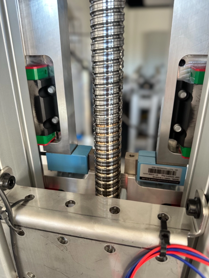
The customer wanted a machine with four independently driven linear axes with a maximum lifting force of 15,000 N each on three axes, whereby the fourth axis was a special axis with significantly different requirements. Certain axes were to be equipped with two force sensors each in order to be able to accurately measure the actual applied push / pull force as well as limit switches for precise referencing.
As the machine was also to be sold in the USA in the future, a decentralized motor control with 48 VDC was required.
CONCEPT & ROLES
As a predecessor machine already existed, we first analyzed its features and hardware problems and carried out a risk analysis to ensure that all specifications were recorded. As the development time was short and the machine complex, we worked with an external design engineer provided by the customer. We were responsible for approving the mechanical implementation, the drive technology and all electrical engineering tasks.
technical Approach
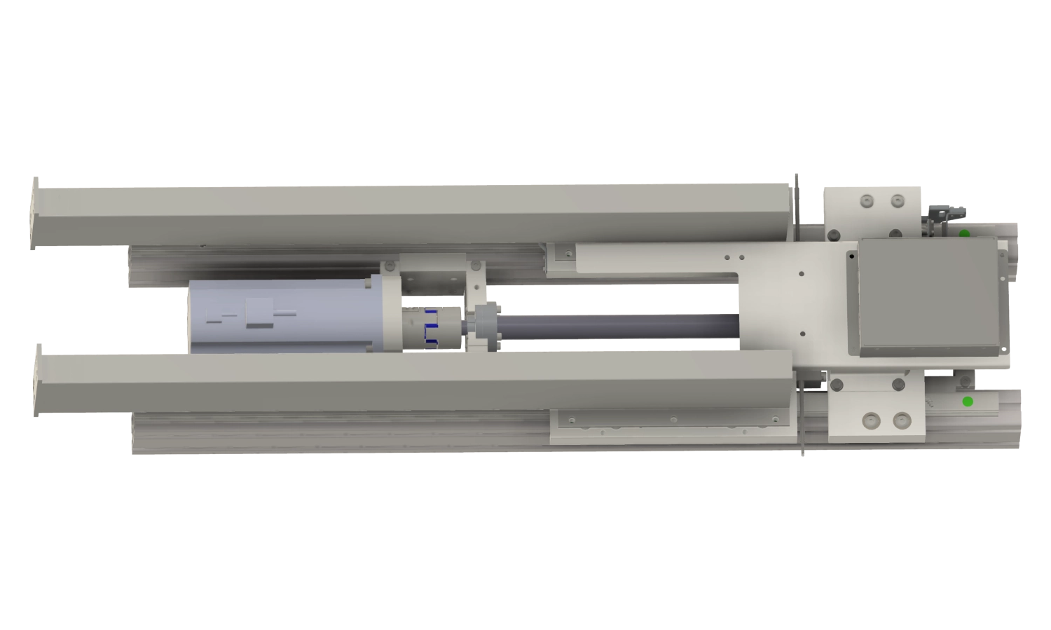
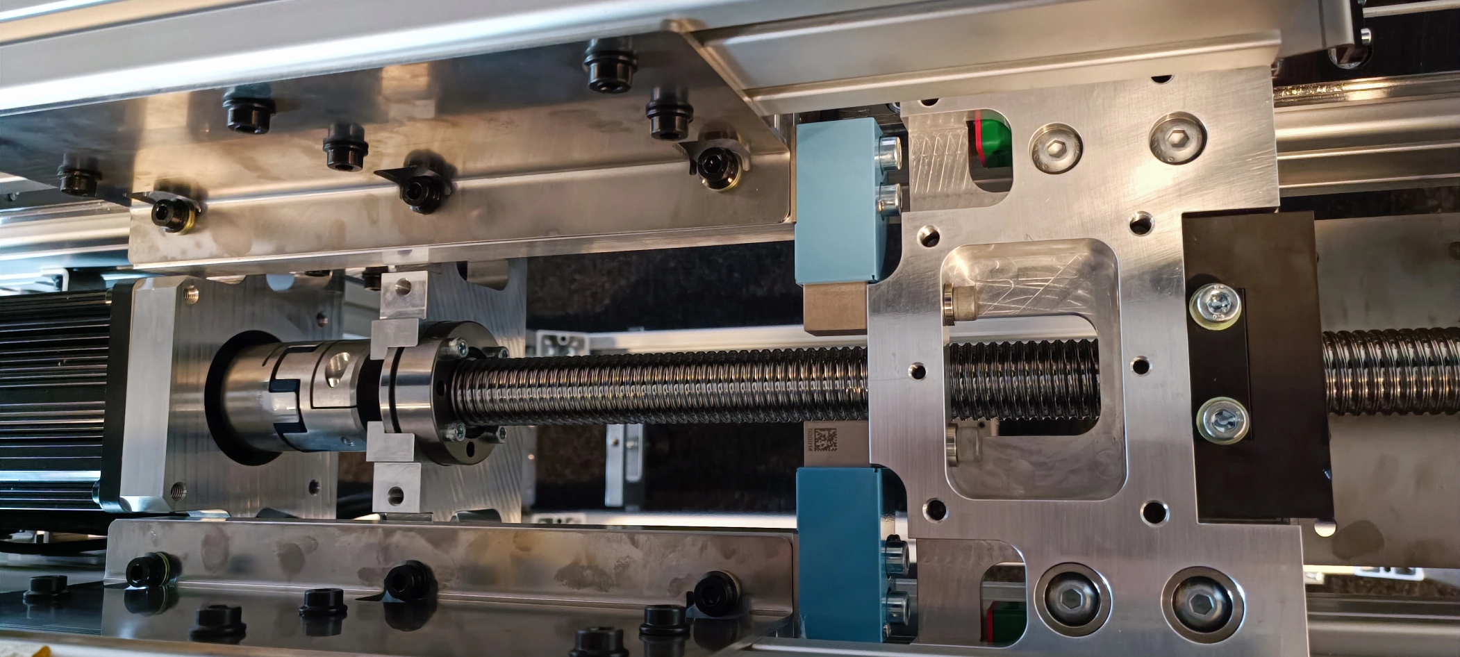
Due to the high forces, three axes were built with ball screws (KGT) and the fourth, very short axis with low forces with a trapezoidal thread with automatic lubricator. In order to reduce production costs, the mechanics had to be able to compensate for manufacturing tolerances; among other things, the carriages were mounted on floating bearings.
We were allowed to design and produce several electronic circuit boards per device for the order. Our X1 motor controller was specifically adapted and predefined behaviors were programmed in directly. Each axis was equipped with an electrical box (see picture above) so that only CAN and the power supply had to be connected to the axes. Peripherals such as the force sensors are plugged directly into the respective box; brake choppers protect against overvoltage in the intermediate circuit during braking.
Testing
The individual subcomponents were tested independently of each other in order to gain early insights. A dev kit was set up consisting of an axis, limit switches and the sensors to develop and test both the firmware and the software for controlling the machine.
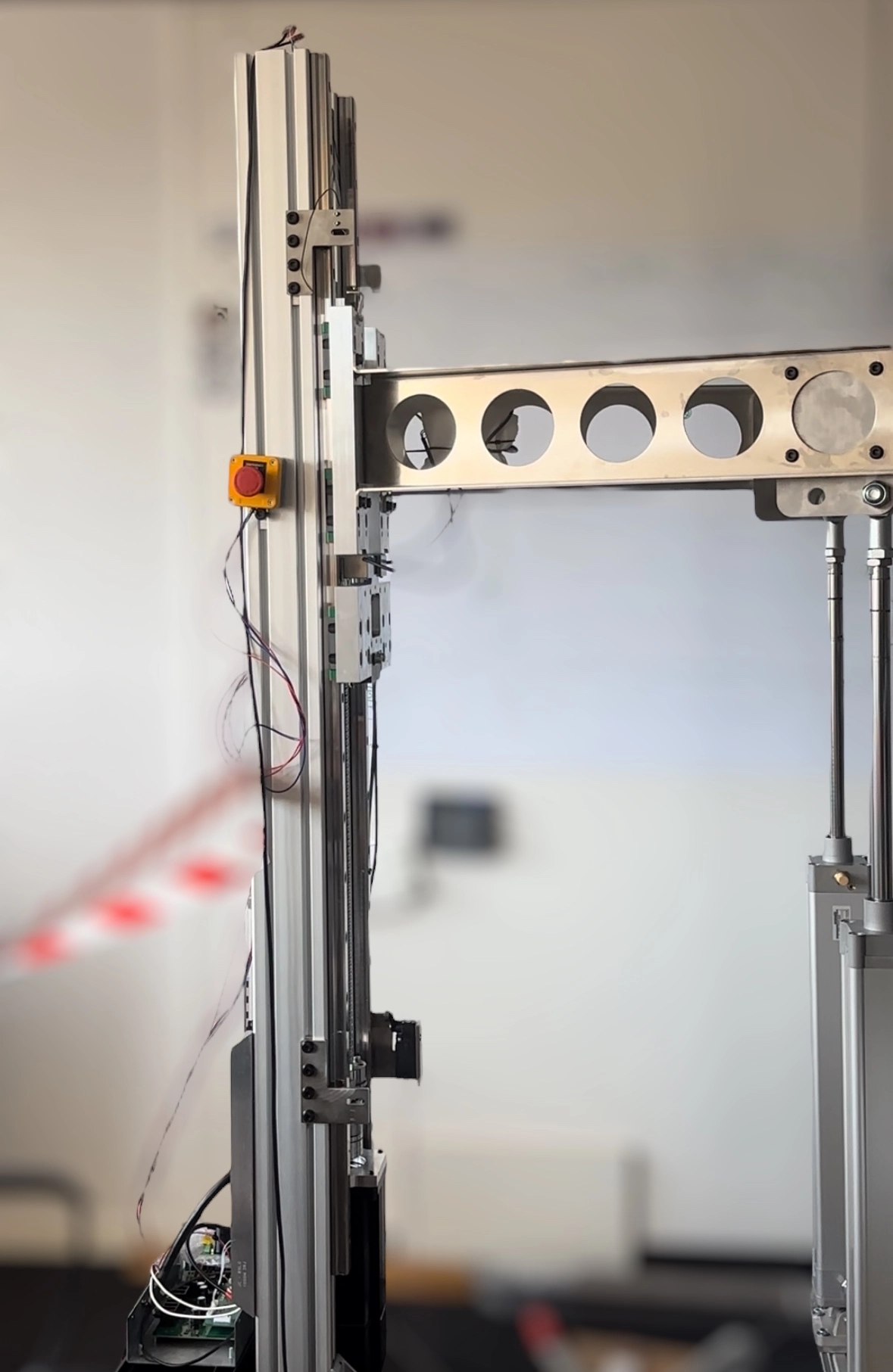
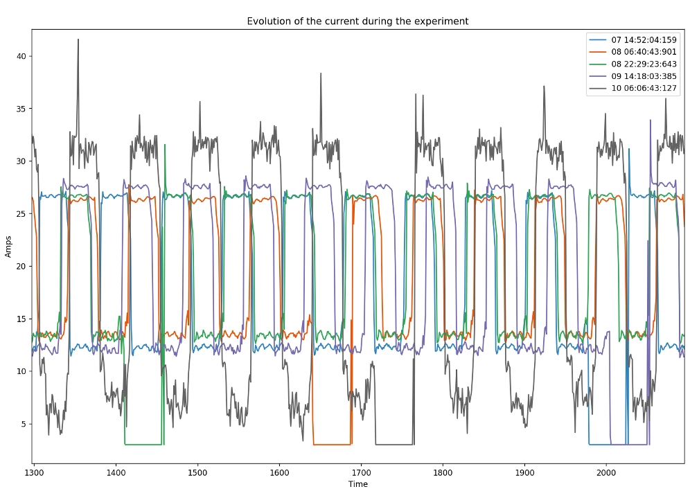
A functional model was created before the first prototypes. The counterforce was generated using pneumatic cylinders and an endurance test of 100,000 cycles was carried out. Thanks to the high data rate of up to 300 measuring points per second (double force measurement, position, speed and current), the smallest changes such as an increase in friction could still be detected and subsequent mechanical damage avoided. The test results were incorporated into further mechanical development.
.webp)

